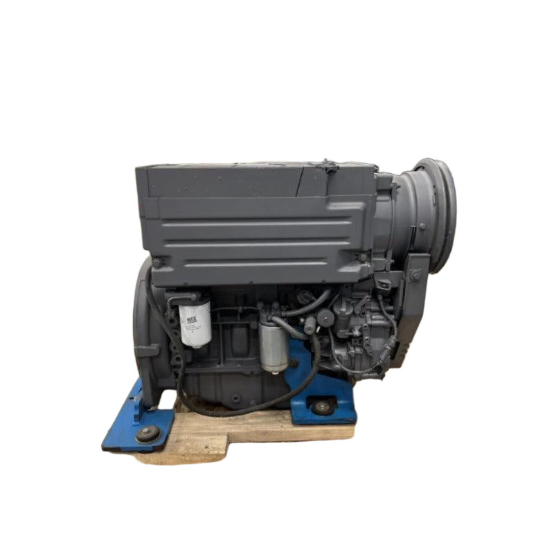
Engine Assembly Description
This Engine Assembly is indexed for Part Number; 1.The magnetic speed sensor is mounted in the ring gear case or flywheel bell housing of the engine. 2.The threaded hole for the speed sensor should be perpendicular to the centerline of the crankshaft and centered over the ring gear teeth. 3.A spot face should be present to provide a flat surface on which to anchor the locknut. 4.With the engine stopped, screw the speed senor in until it touches a gear tooth, then back it out 3/4 of a turn and secure it with the locknut. 5.Any ferrous gear may be used as long as the frequency and amplitude of the resulting signal meet the speed control unit specifications. 6.The wire leads should be twisted for their entire length from the magnetic speed sensor to the control unit. 7.The leads may need shielding if they are longer than 10 ft. (3m), or if external interference is present. 8.Do not connect either of the speed sensor leads to anything but the speed control unit used. The shield should not be connected at the speed sensor end.; Rotary Speed Sensor Hot Parts. Compare reference number MSP676 against the label on your existing 1.the component before ordering.
Additional cross references on file: 8-18, UNF-2A, 1.The. If your machine plate shows a different number, submit a fitment inquiry with photos before checkout.